Solar Power Inverters and EMI Filtering
By James Finn ©2023
Whether you are an electrical engineer, an electrician, or a homeowner considering a new solar power system installation, or you already own one, you will eventually need to deal with the resultant electromagnetic interference, EMI.
Regardless of the term you prefer, Signal-to-Noise Ratio (S/N or SNR), THD+N (Total Harmonic Distortion Plus Noise), harmonic transients, ripple, or “dirty electricity,” solar systems emit high amplitudes of transient harmonic voltages from semiconductor switching onto an electrical system, often interfering to varying degrees with the function of your appliances, electrical devices, electronics, and, eventually onto you.
(The basic physics formulas that describe this process are: Δv/Δτ and Δi/Δτ, where Δ = change, τ = time interval, v = voltage differences, i = current differences.)
Alternative energy is now more popular than ever, and there is much to learn. In the next few months, I plan to share essential knowledge about each type and how to mitigate the electromagnetic interference they produce.
Solar Power is by far the alternative energy source most often asked about. Solar panels produce direct current (DC) electricity, which is incompatible with the alternating current (AC) electricity used in homes. To use the electricity produced by solar panels, it must be converted from DC to AC.
Here is the basic process to convert solar energy into usable AC electricity for a home:
Sunlight: The sun provides the energy source for the solar photovoltaic cells.
Solar Photovoltaic Cells: The photovoltaic cells within a series of photovoltaic (PV) panels are installed on the roof or in a suitable location with unobstructed access to sunlight. The panels convert the sunlight into direct current (DC) electricity.
DC to AC Inverter: The DC electricity from the panels is sent to a solar inverter, which converts the DC electricity into alternating current (AC) electricity. The inverter is typically located near the electrical service panel in the home.
Electrical Service Panel: The AC electricity is then sent to the home's electrical service panel, which is then distributed to the various electrical branch circuits in the home.
Energy Metering: A bi-directional meter is installed to monitor the flow of electricity between the home and the electrical grid. This meter allows the homeowner to determine how much electricity is being produced by the solar panels and how much is being drawn from the grid.
Electrical Grid Connection: The home is connected to the electrical grid through a power company-owned utility line. This allows the home to receive electricity from the grid when the demand exceeds the supply from the solar panels and to send excess electricity back to the grid when the panels are producing more electricity than the home is using.
ESS: (Energy Storage System) is a device that stores excess energy generated by a solar power system. The stored energy can be used later to meet the energy demand when the solar panels are not producing enough energy (e.g., during nighttime or cloudy conditions). An ESS typically consists of batteries or other energy storage technologies and may include power electronics and control systems. Using an ESS can increase the overall efficiency of a solar power system and provide a more reliable and stable energy supply.
Some popular brands and models of ESS for home use:
Tesla Powerwall: This is a lithium-ion battery system designed for residential use and is one of the most well-known ESSs on the market.
LG Chem RESU: This is a high-capacity lithium-ion battery system compatible with a wide range of inverters and can be easily integrated into a home solar power system.
Sonnen: Sonnen offers several ESS models for residential use, including the SonnenBatterie and the SonnenCore. These systems are designed to work with solar panels and provide energy storage and backup power.
Enphase Energy Storage System: This is a modular battery system that can be added to an existing Enphase solar power system. It uses lithium-ion batteries and has a scalable design, making it suitable for homes of different sizes.
These are just a few examples of ESSs available for residential use. When choosing an ESS for your home, it's important to consider factors such as capacity, compatibility with your existing solar power system, and the local regulations and incentives for energy storage.
(A licensed electrical contractor should be consulted for a detailed design and installation to ensure compliance with local codes and standards.)
The conversion process is accomplished by using an inverter. An inverter takes the DC electricity from the solar panels and converts it into AC electricity. The inverter is usually installed near the solar panels and is connected to the panels through cables. The DC electricity from the panels flows into the inverter and is then converted into AC electricity.
When choosing an inverter, it is important to consider the following factors:
Power capacity: The inverter must have the capacity to handle the amount of electricity produced by the solar panels.
Efficiency: An efficient inverter will produce less heat and more efficiently convert DC to AC electricity.
Grid compatibility: Inverters are designed to be compatible with the electrical grid in your area. It is important to choose an inverter that is compatible with your local electrical grid.
Size: The inverter must be appropriately sized for the amount of electricity produced by the solar panels.
By converting DC solar to AC electricity, homes can use the clean and renewable energy produced by their solar panels to power their homes. This not only reduces their carbon footprint but also saves on electricity costs.
Reducing line noise or Electromagnetic Interference (EMI) is integral to the DC-to-AC conversion process.
Here are a few steps that can be taken to reduce EMI:
Proper grounding: Ensure that the inverter is properly grounded to minimize the risk of EMI.
Quality components: Use high-quality components in the inverter circuit to reduce EMI.
Shielding: Shield the inverter and cables with metal casing or braided shielding to reduce the emission of EMI.
Ferrite beads: Place ferrite beads on the DC and AC cables to absorb EMI.
Filtering: Implement appropriate filtering in the inverter circuit to reduce EMI.
Proper installation of the inverter and cables will also reduce EMI.
Reducing EMI is important to ensure that the electrical system remains stable and does not interfere with other electrical equipment. By taking these steps, you can reduce the risk of EMI and ensure that your DC to AC-conversion process is efficient and reliable.
Here are a few EMI filters commonly used in DC to AC conversion applications:
Common-Mode Choke: A common-mode choke is a type of inductor placed on the DC and AC cables to absorb EMI. It is typically used in pairs, one placed on the positive line and one on the negative line, to reduce the common-mode noise on both lines. The choke consists of a wire coil wound around a magnetic core. The magnetic core is designed to increase the coil's inductance, which helps reduce the flow of high-frequency noise.
A common-mode choke provides a low impedance path for the common-mode noise, which helps reduce the amount of noise transmitted from the power source to the equipment. The choke acts as a filter, absorbing the high-frequency noise and reducing the amount of EMI in the system.
Common-mode chokes are a simple, effective, and reliable solution for reducing EMI in electrical systems and are widely used in various applications, such as DC to AC power inverters, power supplies, and motor drives. They are particularly useful in applications with high common-mode noise, providing a cost-effective solution for reducing this noise.
Pi Filter: A Pi filter is a type of LC filter placed on the AC output of the inverter to reduce EMI. It is a passive circuit that consists of two inductors (L) and two capacitors (C) arranged in a Pi configuration.
The Pi filter works by reducing high-frequency noise in the system. The inductors act as choke coils, limiting the flow of high-frequency noise, while the capacitors act as bypasses, short-circuiting the high-frequency noise and passing it to ground.
The Pi filter is often used in applications where the requirement for EMI reduction is high, such as in DC to AC power inverters, power supplies, and motor drives. The Pi filter can be customized to meet the application's specific requirements, such as the frequency range and the level of EMI reduction required.
The Pi filter is a simple, cost-effective, and reliable solution for reducing EMI in electronic systems. It is widely used in various applications and is considered a standard solution for EMI reduction.
Common-Mode Filter: A common-mode filter is a type of filter that is placed on the AC output of the inverter to reduce EMI. A common-mode filter is an EMI (Electromagnetic Interference) filter used to suppress common-mode noise in electrical systems. It works by suppressing the differential-mode noise and passing the common-mode noise through capacitors and inductors.
The components of a common-mode filter include:
Chokes (Inductors): These components limit the flow of high-frequency noise.
Capacitors: These components provide a low-impedance path to ground for high-frequency noise.
Ferrite Beads: These components act as high-frequency low-pass filters and provide additional EMI suppression.
The common-mode filter is connected in parallel with the power or signal lines to be protected, with the positive side connected to one line and the negative side connected to the other line. The combination of inductors and capacitors in the filter creates a low-impedance path for common-mode noise, effectively filtering it out of the signal.
Line Filter: A line filter is an EMI filter placed on the AC input of the inverter to reduce EMI. These filters can be selected based on the specific requirements of the application, such as the amount of EMI reduction required, the type of electrical equipment that needs to be protected, and the cost and availability of the filters. Usually, a combination of these filters is used to achieve the desired level of EMI reduction.
A line filter is typically placed between the power source and the equipment being powered to reduce the amount of high-frequency noise transmitted from the power source to the equipment. Line filters are an effective and reliable solution for reducing EMI in electrical systems and are widely used in various applications.
A typical Line Filter consists of the following components:
Inductor(s): One or more inductors are used to limit the flow of high-frequency noise, which acts as a choke coil.
Capacitor(s): One or more capacitors are used to short-circuit the high-frequency noise, which acts as a bypass.
Resistor(s): One or more resistors are used to provide damping to the filter, which helps to reduce ringing and overshoot.
Metal casing: The components are housed in a metal casing to provide shielding and to reduce the emission of EMI.
The number and values of the components can vary depending on the application's specific requirements, such as the frequency range and the level of EMI reduction required. Line filters can also be designed to meet specific equipment requirements, such as motor drives, power supplies, and DC to AC inverters.
Differential-Mode Filter: A differential-mode filter is placed on the DC input of the inverter to reduce EMI. A differential-mode filter is another EMI (Electromagnetic Interference) filter that reduces noise in electrical systems. It is designed to reduce the differential-mode noise between two lines, such as the positive and negative lines in a power supply.
A Differential-Mode Filter typically consists of the following components:
Inductor(s): One or more inductors are used to limit the flow of high-frequency noise, which acts as a choke coil.
Capacitor(s): One or more capacitors are used to short-circuit the high-frequency noise, which acts as a bypass.
Resistor(s): One or more resistors dampen the filter, which helps reduce ringing and overshoot.
Again, the number and values of the components can vary depending on the application's specific requirements, such as the frequency range and the level of EMI reduction required. The inductors limit the flow of high-frequency noise, while the capacitors short-circuit the high-frequency noise and pass it to ground. The resistors provide damping, which helps to reduce ringing and overshoot.
There are several types of inverters used to convert DC to AC, including:
Square Wave Inverter: generates a square wave output with abrupt transitions between the positive and negative voltages.
Advantages: Simple design, low cost.
Disadvantages: Poor power quality, increased harmonic distortion, inefficient operation of some electrical devices.
Modified Sine Wave Inverter: generates a waveform that approximates a sine wave, with smoother transitions than a square wave.
Advantages: Improved power quality compared to a square wave inverter and lower cost compared to a pure sine wave inverter.
Disadvantages: Still inferior power quality compared to a pure sine wave inverter, increased harmonic distortion.
Pure Sine Wave Inverter: generates a waveform that is a close representation of a true sine wave.
Advantages: High power quality, efficient operation of all electrical devices, low harmonic distortion.
Disadvantages: More complex and expensive design compared to other types.
Pulse Width Modulation (PWM) Inverter: uses digital signals to generate an AC output by switching the DC voltage on and off at a high frequency.
Advantages: High power quality, high efficiency, and low harmonic distortion.
Disadvantages: Complex design, the higher cost compared to other types.
A Pulse Width Modulation (PWM) Inverter typically consists of the following components:
DC source (e.g. battery)
Power electronic switches (e.g. MOSFETs, IGBTs)
Inductor or transformer
Capacitor
Control circuit (e.g. microcontroller, gate driver circuit)
Protection circuit (e.g. over-voltage, over-current)
Output filter to smooth the PWM waveform into a sinusoidal waveform.
A MOSFET (Metal-Oxide-Semiconductor Field-Effect Transistor): is a power electronic switch that controls the flow of electric current by using an electric field. MOSFETs are widely used in inverters due to their fast switching speeds, high efficiency, and simple drive requirements. (More info on MOSFETs in the Addendum.)
An IGBT (Insulated-Gate Bipolar Transistor): is another power electronic switch that combines the benefits of a bipolar transistor and a MOSFET. IGBTs are capable of handling high current and voltage levels, and they have fast switching speeds like MOSFETs. This makes them ideal for high-power inverter applications where high efficiency and high power density are desired. (More info on IGBTs is in the Addendum.)
The Protection Circuit in a PWM inverter is designed to prevent damage to the inverter components and to ensure the safe operation of the system. Protection circuits are typically used to detect and respond to over-voltage, over-current, short-circuit, and thermal conditions.
Over-Voltage Protection: Detects and responds to high voltage levels in the inverter output, which can damage the components or cause safety issues.
Over-Current Protection: Detects and responds to high current levels in the inverter output, which can cause overheating and damage to the components.
Short-Circuit Protection: Detects and responds to a short-circuit condition in the inverter output, which can cause high current levels and damage the components.
Thermal Protection: Detects and responds to high-temperature levels in the inverter components, which can cause overheating and permanent damage.
When these protection events occur, the protection circuit typically shuts down the inverter operation or reduces the output power to prevent further damage. The protection circuit is an important component in ensuring the safe and reliable operation of the PWM inverter.
In a Pulse Width Modulation (PWM) inverter, the type of capacitor is typically an electrolytic capacitor. These capacitors are used in the output filter circuit to smooth the PWM waveform into a sinusoidal waveform. The capacitance value and voltage rating of the capacitor depending on the power rating and operating conditions of the inverter.
Electrolytic capacitors are preferred for PWM inverters because of their high capacitance density and relatively low cost. Additionally, electrolytic capacitors have a relatively low equivalent series resistance (ESR), which is important for reducing switching losses and improving the overall efficiency of the inverter.
Other types of capacitors, such as tantalum capacitors, may also be used in PWM inverters. However, these capacitors are typically more expensive and have lower capacitance density than electrolytic ones.
In a Pulse Width Modulation (PWM) inverter, the type of transformer is typically an isolation transformer. The purpose of the isolation transformer is to provide electrical isolation between the input DC voltage and the output AC voltage.
The isolation transformer serves several important functions in the PWM inverter, including:
Reducing the voltage stress on the power electronic switches.
Improving the safety of the inverter by preventing electrical shock and fire hazards.
Reducing electromagnetic interference (EMI) generated by the inverter.
Isolation transformers are designed with specific characteristics based on the power rating and operating conditions of the inverter. The primary winding is connected to the input DC voltage, while the secondary winding is connected to the output AC voltage. The transformer's turn ratio is designed to step up or down the voltage to the desired level.
The isolation transformer is an important component in ensuring the reliability and performance of the PWM inverter.
A Pulse Width Modulation (PWM) inverter typically uses an LC (Inductor-Capacitor) output filter to smooth the PWM waveform into a sinusoidal waveform. The LC filter consists of an inductor and a capacitor connected in series or parallel. The LC filter is designed to reduce the harmonic content of the PWM waveform by filtering out high-frequency components and passing the desired sinusoidal waveform.
The LC Filter removes high-frequency harmonic content from the output waveform of the inverter, resulting in a smoother, more sinusoidal waveform. The inductors store energy and block the high-frequency harmonics, while the capacitors serve to smooth the waveform and prevent high-frequency oscillations.
The type of LC filter used in a PWM inverter depends on the power rating, operating frequency, and other specifications of the inverter. The LC filter components are selected based on their frequency response, impedance, and stability characteristics.
The LC filter is an important component in ensuring the performance and efficiency of the PWM inverter by improving the waveform quality and reducing harmonic distortion.
Examples of LC filters used in PWM inverters include:
Series LC Filter is a type of output filter used in power electronics to smooth and shape the output waveform of a power inverter. It comprises an inductor (L) and a capacitor (C) connected in series.
A series LC filter is a simple and effective way to improve the waveform quality of a power inverter. However, it may not be as effective in removing high-frequency harmonics as a more complex filter, such as a cascaded LC filter or a Pi filter.
Series LC filters are commonly used in low-power applications where a simple, low-cost solution is desired, such as small inverters or battery chargers.
Parallel LC Filter is a type of output filter used in power electronics to smooth and shape the output waveform of a power inverter. It comprises an inductor (L) and a capacitor (C) connected in parallel.
The LC filter removes high-frequency harmonic content from the output waveform of the inverter, resulting in a smoother, more sinusoidal waveform. The inductor blocks high-frequency harmonics and the capacitor serves to smooth the waveform and prevent high-frequency oscillations.
A parallel LC filter is a simple and effective way to improve the waveform quality of a power inverter. A parallel filter may not be as effective in removing high-frequency harmonics as a more complex filter, such as a series LC filter or a Pi filter.
Parallel LC filters are commonly used in low-power applications where a simple, low-cost solution is desired, such as small inverters or battery chargers.
Cascaded LC Filter is a type of output filter used in power electronics to smooth and shape the output waveform of a power inverter. It is comprised of multiple stages of inductors (L) and capacitors (C) connected in series, hence the name "cascaded LC filter."
In a cascaded LC filter, multiple stages of LC components are used to filter the output waveform better. This improves the waveform quality, reduces harmonic distortion, and improves the power inverter's overall efficiency and reliability.
Cascaded LC filters are commonly used in applications that require a clean and stable output waveform, such as uninterruptible power supplies (UPS), renewable energy systems, and motor drives.
A Pure Sine Wave Inverter consists of the following components:
DC-AC Converter: Converts the input DC voltage into a sinusoidal AC voltage.
Output Filter: Smooths the AC waveform and reduces harmonic content.
Control Circuit: Regulates the output voltage and frequency and monitors the inverter for protection events.
The DC-AC Converter in a pure sine wave inverter typically uses the carrier-based pulse width modulation (PWM) technique. This technique converts the DC voltage into a high-frequency sinusoidal waveform, filtered and amplified to produce the desired AC voltage.
A Pure Sine Wave Inverter is a type of inverter that converts direct current (DC) into a sinusoidal alternating current (AC) waveform. Unlike a Pulse Width Modulation (PWM) inverter, which generates a square waveform that resembles a sinusoidal waveform, a pure sine wave inverter generates a true sinusoidal virtually indistinguishable from a utility-supplied AC waveform.
Compared to a PWM inverter, a pure sine wave inverter typically has a more complex control circuit and requires more sophisticated components, such as high-frequency power transistors and specialized output filters. However, the output waveform quality of a pure sine wave inverter is significantly better than that of a PWM inverter, making it suitable for applications that require a clean, reliable power source.
In addition to its improved waveform quality, a pure sine wave inverter provides improved efficiency, reduced noise, EMI, and better compatibility with sensitive loads, such as computers and audio equipment.
Some popular brands and models of Pure Sine Wave Inverters include:
Victron Energy Phoenix Inverters
Outback Power FlexMax Inverters
Xantrex Freedom Inverters
Schneider Electric XW Inverters
SMA Sunny Boy Inverters
EcoFlow Delta Inverter Generators
Inverter Generators by Yamaha and Honda
These brands and models offer a range of power ratings and features, including compact design, high efficiency, low noise, and remote monitoring capabilities. These inverters are widely used in various applications, including off-grid and mobile power systems, backup power, and commercial and industrial power solutions. The specific model and brand will depend on the user's requirements and application.
Some popular brands and models of Pulse Width Modulation (PWM) inverters include:
PowerBright PW1100-12
KRIËGER 1100 Watt 12V Power Inverter
Energizer EN1100
AMPEAK 1000W Power Inverter
BESTEK 500W Power Inverter
Go Power! GP-SW1000-12
AIMS Power PWRI110012
These brands and models offer a range of power ratings and features, including compact design, high efficiency, low noise, and remote monitoring capabilities. These inverters are widely used in various applications, including off-grid and mobile power systems, backup power, and commercial and industrial power solutions. The specific model and brand will depend on the user's requirements and application.
Addendum:
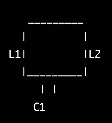
The Pi Filter is a type of output filter used in power electronics to smooth and shape the output waveform of a power inverter. It gets its name from its shape, which resembles the Greek letter "π" and consists of two inductors (L) and a capacitor (C) connected in a specific arrangement. The inductors block high-frequency harmonics, while the capacitor serves to smooth the waveform and prevent high-frequency oscillations.
Pi Filter diagram © 2023
In the diagram, L1 and L2 represent the inductors, and C1 represents the capacitor. The inductors are connected in series, with their common connection connected to the capacitor. The other terminal of L1 is connected to the inverter output, while the other terminal of L2 is connected to ground. The other terminal of the capacitor is also connected to the inverter output.
The topology of a Pi filter can be represented as follows: two inductors are connected in series, with the common connection of the two inductors being connected to a capacitor. The other terminal of the first inductor and the other terminal of the capacitor is connected to the inverter output. In contrast, the other terminal of the second inductor is connected to ground.
The Pi filter is a more complex and effective filter than a series LC filter or a parallel LC filter. It is commonly used in applications that require a clean and stable output waveform, such as uninterruptible power supplies (UPS), renewable energy systems, and motor drives.
MOSFET Diagram © 2023
2. The operation of the MOSFET is based on the flow of charge carriers (electrons or holes) through a channel between the source and the drain, which is controlled by the voltage applied to the gate terminal. The gate terminal is insulated from the channel and is connected to the body, allowing the charge carriers to flow between the source and drain.
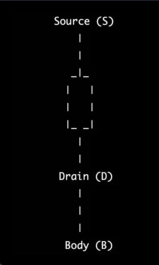
MOSFET diagram © 2023
Here is a diagram that represents the basic structure of a MOSFET. In the diagram, the MOSFET has three terminals: the source (S), the drain (D), and the body (B). The source and drain form the input/output of the MOSFET, while the body is connected to the substrate or the source.
When a positive voltage is applied to the gate terminal, it attracts electrons and forms an inversion layer in the channel, which enhances the conductivity between the source and drain. When a negative voltage is applied to the gate terminal, it repels electrons and reduces the conductivity between the source and drain.
MOSFETs are widely used in power electronics due to their high input impedance, fast switching speed, and low on-state resistance, making them ideal for high-frequency switching applications, such as PWM inverters.
3. IGBTs are widely used in power electronics due to their high voltage and current capabilities, fast switching speed, and low on-state voltage drop, making them ideal for high-power switching applications, such as PWM inverters and UPS systems.
The operation of the IGBT is based on the flow of charge carriers (holes and electrons) between the emitter and collector, which is controlled by the voltage applied to the base terminal. When a positive voltage is applied to the base terminal, it causes holes to flow from the emitter to the base, creating a high current flow from the collector to the emitter, turning on the IGBT. When the voltage is removed from the base, the holes stop flowing, turning off the IGBT.
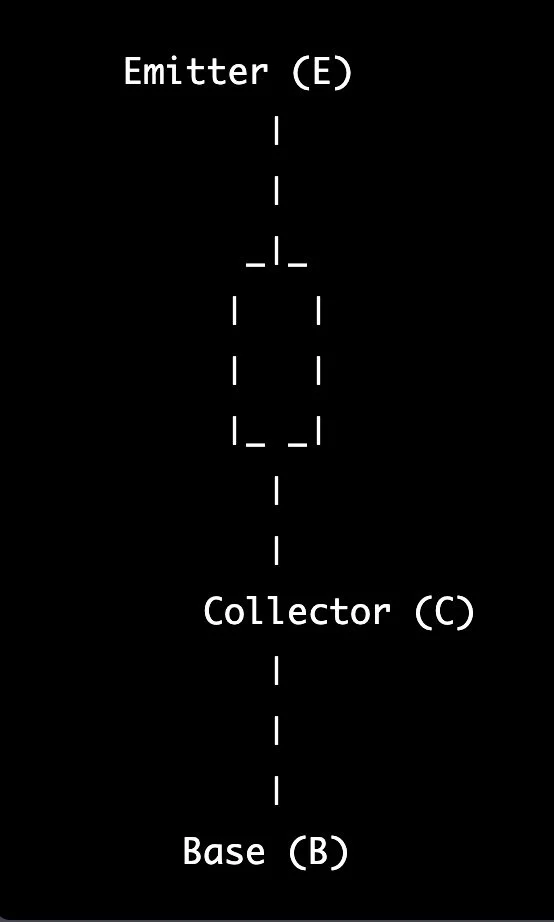
IGBT diagram © 2023
Here is a diagram that represents the basic structure of an IGBT. In the diagram, the IGBT has three terminals: the emitter (E), the collector (C), and the base (B). The emitter and collector form the input/output of the IGBT, while the base is connected to the p-n junction of the device.
What are the potential long-term drawbacks of using solar power for a home?
Here are some potential long-term drawbacks of using solar power for a home:
Initial Costs: Installing a solar energy system can be expensive, ranging from $10,000 to $30,000. This may make it less accessible for some homeowners, especially those on a tight budget.
Maintenance: Solar panels require regular cleaning and maintenance to maintain their efficiency. This may require homeowners to invest time and money into keeping their systems in good working order.
Location Dependency: The efficiency of solar panels can be affected by weather conditions, such as cloud cover, dust, and other environmental factors. This means that homeowners may experience reduced energy generation during inclement weather.
Energy Storage: Solar panels generate electricity during daylight hours but may not generate enough energy to meet the needs of a home during periods of low light or at night. This means that homeowners may need to invest in energy storage systems, such as batteries, to ensure that they have a reliable energy source when needed.
Incompatible with Older Homes: Solar panels may not be suitable for older homes with limited roof space or outdated electrical systems and may require homeowners to make significant upgrades to accommodate the technology.
Interference with Other Technologies (if you do not preemptively remediate EMI): Solar panels may interfere with other technologies, such as radio or television signals, or cause electromagnetic interference. This may result in performance issues or other problems that can be difficult and expensive to resolve.
It is important to note that these potential drawbacks will vary depending on the specific system, location, and other factors. Before choosing a solar energy system, it is important to carefully consider the costs, benefits, and potential drawbacks of the technology and to work with a licensed and experienced contractor to ensure the quality and safety of your installation.
What are the long-term benefits of using solar power for a home?
Here are some long-term benefits of using solar power for a home:
Cost Savings: By generating their electricity, homeowners who use solar power can reduce their dependence on traditional energy sources, such as the grid, and save money on energy bills over time.
Energy Independence: Solar power systems allow homeowners to generate their electricity, making them less dependent on traditional energy sources, such as the grid. This can provide greater energy security, especially in areas where power outages are common.
Environmentally Friendly: Solar power is a clean and renewable energy source that produces no emissions or pollution. This makes it an environmentally friendly option for homeowners who want to reduce their carbon footprint.
Low Maintenance: Solar panels are low maintenance and require minimal cleaning and upkeep, making them a hassle-free option for homeowners who want to generate their electricity.
Increase Property Value: Homes equipped with solar power systems are often seen as more valuable and appealing to potential buyers, which can increase the property's value over time.
Federal and State Incentives: There are federal and state tax credits, rebates, and other incentives available for homeowners who install solar power systems, which can help offset the initial costs of installation and make the technology more accessible.
It is important to note that the specific benefits of using solar power to electric power a home will depend on the specific system, location, and other factors. Before choosing a solar energy system, it is important to carefully consider the costs, benefits, and potential drawbacks of the technology and to work with a licensed and experienced contractor to ensure the quality and safety of your installation.
©2023 All rights are reserved.
