Journal | EMF-EMI Information Elexana LLC

ELEXANA Contact Portal

EMI Mitigation: How and Why are Electric Fields Measured?

Elexana-measuring-electric-fields.jpeg

One reason an engineer can fail to solve an EMI issue is that she or he does not consider the potential impact of capacitive coupling attributed by E-Fields (electric fields.)

When we assess E-Fields, we are referring to measuring the electron particle component of electromagnetism in terms of voltage separated from the perpendicular, or vector, magnetic flux "lines-of-force" component of A.C. (alternating current.) The standard frequencies of electrical power are 50 Hertz (European) or 60 Hertz (North American), 5 Hertz (European Railways), 25 Hertz for the Traction Power Grid for New Jersey Transit and Amtrak (60 Hz for the New Haven Line), and the Siemen’s Sitras Brand which uses AC and DC.

Most think that electricity travels within the electrical cabling and is wholly contained within these metal conductors, whether they be transmission lines, distribution lines, facility wiring, or equipment and appliance electrical cords. However, an electrical conductor functions merely as a guide. The larger the load on this conductor, the more spread the field. The girth of the electric field around the conductor will depend on how well the overall electrical system is contained and grounded, as well as the resistance of the soil of Earth's ground.

There are four possible relationships between the electric and magnetic aspects of electricity. You can have: 

  1. a strong electrical component with a weak magnetic flux, or 

  2. a weak electric component with a strong magnetic flux, or 

  3. both relatively weak, or 

  4. both relatively strong. 

    We identify and measure these aspects separately because the remedial solutions are very different.

 We mitigate E-Fields by proper Earth grounding versus Magnetic Fields which need to be either:

1. canceled by bringing the hot wire (phase conductor) and the neutral return conductor closer together, or 

2. create a literal distance by moving further from the source-point, or 

3. create distance from a source-point via shielding because the magnetic waves have the travel around the shielding thereby weakening. More on all of this later.

If a consultant speaks about EMF as lines of force, and they only show up with a gauss meter and not any tool to measure the E-Fields, then the EMI assessment will be incomplete, and thereby incorrect, if not accounting for the potential of capacitive coupling. E.P.R. Electron Paramagnetic Resonance and the Stark Effect will disrupt superconductors and more.

Human-made alternating current has only been in our world since George Westinghouse began mass-producing electricity. In 1893, Westinghouse Corporation applied massive magnetic transformers to step-up electricity generated by turbines placed at Niagara Falls. With the first installation of its kind, New York State was officially on the power grid. 

Perhaps one of the most insidious forms of non-ionizing radiation resides within our very own home or office walls. Unshielded electrical cabling (Romex) emits an E-Field that is about 6-8 feet. Romex is also an excellent antenna for radiofrequency emissions (RF.) A factory is required to have industrial electrical cable in the walls, however as I just witnessed recently, an outside vendor had installed lighting that was not to code. Unless an electrician has experience working in manufacturing facilities, then they may not know the necessary codes.

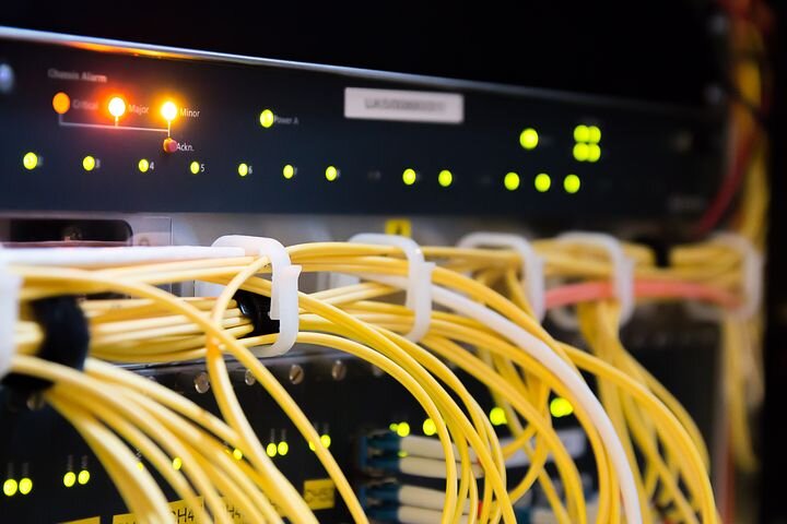
A slight digression: Once RF couples on to active wiring, both line, and airborne electromagnetic interference (EMI) results. EMI causes high-frequency harmonic transients or signal-to-noise (S/N) beyond the fundamental 60 Hertz of our electrical supply. Using oscilloscopes and spectrum analyzers, we measure electromagnetic interference. The more RF wireless devices in the facility, and the more conductive surfaces, then the more EMI will be introduced onto our systems.

Depending on the voltage (V/m), then the more potential impact the EMI will have on equipment.

1. Using an NFA 1000, we measure the potential-free voltage in the air. This tool utilizes a proprietary technology developed by Gigahertz Solutions in Germany, measuring airborne voltage using a triaxial X, Y, and Z pattern sensor array without the need for a ground reference. This method allows us to measure V/m quite efficiently. 

2. A second way is to drive a ground stake into the Earth-ground and take a relative to Earth's ground E-Field measurement.

3. A third method is to measure the actual voltage coupling to the skin. Using a reference ground and grasping a brass bar in the palm, we measure the average potential on the epidermis. The epidermis reacts to the size and strength of the E-Field. This measuring technique is a direct way to evaluate occupational exposure.

At Elexana, we incorporate a third: Using a 3-D sensor array that picks up electrical particles down to 9 kHz, which is the VLF (very low frequency) range; just above the ELF range of our 60 Hertz electricity. With this, we measure the upper harmonic transients of the electrical supply and the electrical aspect of radio frequencies.

Before the NFA 1000, I would go from room to room, measuring my epidermal voltage to determine the size and strength of the E-Fields and determine the level of success of remediation. It was time-consuming but effective. 

EMI Diagnostic work requires a passion for thoroughness, relentless attention to detail, and spontaneous on-demand creativity. It's not for everyone, but if you think that you have these qualities, then with the proper knowledge and training, you could become a talented EMI Consultant.

Share

Know Your EMI Tolerance and EMF Safety Levels Before Hiring an EMF Testing Company

You could need EMI Compliance or EMF Safety tests for all sorts of reasons. Before you jump into the internet search rabbit hole, do some homework based on your needs. 

ELexana-EMF-safety-levels.png

If you need to know if a new piece of equipment will function properly at a new location, then check the manual for EMI tolerance specs. We even had one piece of equipment that required a specific meter be used for the compliance test, or the manufacturer’s guarantee would not be applicable.

If you have a medical device, such as an anesthesia table, then know that there is a specific FDA compliance testing procedure that this little side table must undergo. Be sure that during your manufacturing process, you put the table under the rigors of pre-compliance testing to save you time and money.

Are you interested in RF emissions from an industrial dryer that emits 27-30 MHz of strong RF, then you need to know National IEEE, OSHA, and your particular state’s DEP safety regulations. We recommend also knowing international standards for occupational safety. If one day you wish to partner with a Chinese, Israeli, or European firm, then they may insist that their workers are operating within their own country’s guidelines.

If you wish to buy a new investment property, then you need to not only know the US safety levels, but you also need to know all of the international safety standards. A European or Israeli company is often not concerned with the US safety levels because the standards are so much lower than the rest of the world’s standards. For example, the US safety level for exposure to AC Magnetic Fields is 1,000 mG (milligauss) whereas the Israeli safety level is only 4 mG. Another example; the US/IEEE safety level for radio frequency exposure is 10,000,000 µW/m² whereas much of the world’s safety level including Israel, Germany, France, Russia, and China’s is 10,000 µW/m². Salzburg, Austria’s and Luxembourg’s limits are 1,000 µW/m².

If you wish to have your family residence tested, then you should do some research to know what AC Magnetic, AC Electric, and RF emission levels are acceptable to you. Elexana’s safety limits for residential work are in line with the Building Biology® Institute. We are certified Electromagnetic Radiation Specialists (EMRS). 

Be sure that the EMF Company you are interviewing shares with you their EMF Safety Actionable Levels long before you hire them. If they believe that 10 mG is an acceptable level and 10 mG is what their shielding will leak, then any electron microscopes or scanners will be situated within a magnetic environment that may not meet manufacturer’s specifications.

Wiring error identification is a service that a trained and certified EMRS learns how to provide. It does NOT require an electrical license because it is non-invasive. Wall outlet receptacles or electrical panels do not need opening up to provide this service. 

Every trained EMRS works with an electrician who will then do the follow-up work. We can instruct an electrician on how to troubleshoot and identify problems in a mains or a sub-panel. Our affiliate licensed electricians continue the process we begin, making your home safe from potential electrical fires and AC Magnetic Fields, created by wiring errors, which can cause a possible fire. Often, we see that a more efficient electrical system will lower your monthly utility bill.  

Share

Hand-Held Radio Frequency Meters: Pros vs. Cons

Pros:

Hand-held RF meters are cost-effective and easy to use. Those with a logarithmic periodic antenna are particularly good at identifying general source points, such as smart meters, cellular antenna ports and towers, wifi, cordless phones, BlueTooth, etc. For this reason, the Gigahertz Solutions HF59B and HF59D hand-held meters serve well the excellent work that an Electromagnetic Radiation Specialist, EMRS, provides you. 

The Gigahertz Solutions HF59B, one of the best hand-held RF analyzers (Made in Germany), is most responsive in the ‘Sensitive” setting and measures RF signal power to a resolution of a microwatt per square meter (µW/㎡) for power readings. Unfortunately, it does not take much to overload this setting, so the max settings that bump the measurement units up to a milliwatt per square meter (mW/㎡) are often required. It has a running RMS (Root-Mean-Squared Average) setting and a PEAK and PEAK-hold function that do not average but sum the three highest received peak frequencies. By the FCC, this mathematical method is acceptable as a viable calculation method.

The isotropic antenna (Isotropic is a “donut-shaped” pattern above the antenna) has a typical zero dBi (decibel-isotropic) gain. This means the measurements are relatively linear (consistently representative of the actual signal strength across all frequency bands) and do not require antenna factor calculations. (The logarithmic periodic antennas and all other log-per antennas require compensation calculations because the dipole antennas that make up a log-per antenna resonate with specific frequencies more than others. So, these resonating frequencies will be received better than others. The weaker resonating frequencies will be received as a weaker signal than in reality, so compensation for the signal as measured weaker than it is are needed for those specific frequencies. This compensation is termed the antenna factor, AF.)

DpfU8AcERQ2Dy29xGLfTqA.jpg

Cons:

The typical hand-held meter is a scalar measuring instrument that can exaggerate the measured power density levels. It can also under-measure.

A Gigahertz Solutions RF Analyzer and most hand-held meters can under-record a cell tower measurement. Today’s 5G antenna ports emit five different frequency bands. So, if the analyzer is only summing three of the highest amplitudes, it will not account for the two bands with weaker signals. (The effect of RF on electronics and persons results from power density and other factors such as frequency, phase modulation, pulse amplitude variations, and distortion.)

In addition, because these meters cannot measure phase, any impedance mismatches and reflections can add in and out-of-phase distortion with the incident signal you are measuring, resulting in magnitude uncertainty. This typically occurs while measuring inside any room or on a New York City block because of multiple reflective surfaces. An EMRS is aware of this issue while measuring indoors and tries to account for this during the assessment.

Most hand-held RF meters are broadband and not frequency selective. As a result, all unwanted signals caused by the meter’s circuitry will get averaged into the measurement, often causing false or inaccurate readings. This is why we throw out spike readings that do not correspond to a smart meter’s demodulated audio signal.

Intermodulation resultants are signals generated by nonlinear interactions within the transmitter components. For example, the internal mixer which processes the RF signal has a nonlinear behavior. The mixer outputs the sum and difference of three input signal frequencies via diode sensors, and then the output is isolated. Most high-end meters have an IF Filter (Intermediary Frequency Filter.) The higher frequency summation is a process known as up-conversion, meaning that the output frequency is higher than the second input frequency.

The problem with using any mixer within the circuitry path is that mixers can present signal combinations along with their harmonics and leakage of the input signals to the output. The frequency and amplitude of the intermodulation resultants will then change with a delta in the input signals, resulting in yet another way to get an incorrect measurement. Care and experience can minimize this effect in specific environments, but it is nearly impossible to avoid in a dense RF environment such as New York City.

We term any unwanted signal as a spurious event or spur. Spurs from internal circuitry leakage and external radiative coupling may occur at any frequency or power level. If you use any hand-held RF meter or hand-held spectrum analyzer, there is a good chance that your peak readings will have spurs. Therefore, we recommend monitoring the RMS (root-mean-squared) readings, taking extended-time measurements, and voiding any one-time spike readings.

Often, you can use your own eyes to locate RF sources unless you are in a big city or a rural area with dense foliage and do not have an FCC mapping of licensed antennas in your vicinity. Generally, a hand-held RF meter is not the correct tool to acquire data for scientific assessments of RF signals, except for a specific few makes and models. Still, meters such as the Gigahertz Solutions HF59B and HF59D will work for general residential work where you want to get a sense of the relative power levels entering your space.

Usually, if you want accurate isotropic broadband measurements for scientific purposes, then either ascertain an isotropic broadband antenna with a dedicated spectrum analyzer or find a hand-held meter that isolates the antenna from the electronics, has internal RF shielding with a built-in attenuator, and monitor the RF signals for a longer time-span.

Calibration and Professional Meters:

A professional meter, for most applications it is designed for, has an up-to-date ISO 17025 calibration certificate. This certification includes a detailed report of the +/- decibel (dB) error or percentage level of uncertainty for each frequency and measurement traceability to a specific up-to-date calibrated tool.

If the meter has a NIST (National Institute of Standards) traceable certification only, then it is helpful as a reference tool but not for taking critical high-risk measurements such as for the aviation industry, industrial safety, pacemakers, etc.

If your meter has a factory calibration, measurements are generally certified by the manufacturer at their stated accuracy for one year. Most measuring equipment used frequently will go out of calibration within one year.

Up-to-date calibration certificates should be included in your report. If you are a professional providing high-risk assessments, we recommend you use ISO 17025 certified-calibrated equipment.

© 2022. All rights are reserved.

Share