
Electromagnetic Interference (EMI)
Simplifying the Basics
by James Finn ©2017, 2022, 2025
Electromagnetic interference is the distortion resultant on to:
An existing electromagnetic field, or
A conductor, which is termed the "receptor." A conductor in the electrical context is any wire that can provide a path for current to flow. In general terms, any metallic object or mass retaining moisture is conductive. A human being or animal can also be a receptor of an electromagnetic radiation source that can cause biological interference with healthy functioning cells.
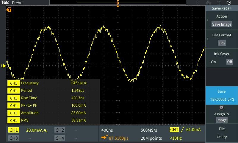
Photo: Screenshot from oscilloscope. We used an oscilloscope with an induction sensor probe to measure EMI on an Apple TrackPad II. If there was no EMI on the DUT (device under test), we would have had a smooth sine wave, instead, it is quite jagged. Notice the 645.9 kHz fundamental. A smooth sine wave would be 60 Hz.
Copyright ©2020
Interference requires:
A noise source (emitter)
A pathway (method of coupling or energy transfer)
A receptor, (a receiver that is susceptible to interference.)
Any Electromagnetic Field Test is ultimately an EMI test because it aims to determine the potential for any specific ambient electromagnetic field to cause interference or obstruction to electrical systems, equipment function, or staff safety.
However, EMI testing goes to even deeper levels. We also look at the specific equipment of concern or under test (EUT) down to the circuit boards and the device’s electrical function, emissions, and electromagnetic compatibility (EMC) when deciding on its best location in your facility.
EMI causes the alteration of waveforms, electron paths, and directions due to the coupling of noise from electromagnetic radiation. How disruptive any interference will be to a receptor depends on its susceptibility and immunity to the interference.
With the exponential increase of wireless technologies worldwide, EMI has become a common vernacular. Synonyms are signal-to-noise ratio (SNR), line noise, harmonic transients, dirty electricity, RFI (radio frequency interference), and electromagnetic coupling.
I prefer electrical engineering terms because they are used by engineers with whom I have to communicate.
The Four Types of Electromagnetic Coupling are:
1. Conductive Coupling occurs when the coupling path between the source and the receptor forms direct electrical contact with a conducting body,
An example of Conductive Coupling occurs when a municipal water service pipe has a reverse neutral stray current, and the lightning protection system ground wire connected to it conducts this neutral current back onto the neutral bus of an electrical panel. Line EMI or signal-to-noise can occur from the same or opposite directions.
When the signal-to-noise ratio appears in phase in the same direction on both conductors, we call this common impedance.
We call this differential impedance when the signal-to-noise ratio appears out of phase, in the opposite direction on both conductors.
2. Inductive Coupling occurs when a strong electromotive force intersects an electrical conductor within a magnetic field, causing the original magnetic field to become distorted. James Clerk Maxwell, who preceded Albert Einstein, mathematically described this process as "Faraday's Law of Induction." An example of inductive coupling is when an underground power line runs close enough to a water pipe that the pipe acquires leakage current.
3. Capacitive Coupling occurs when two fluctuating electrical fields co-exist between two adjacent conductors, thereby inducing a change in voltage on the receiving conductor receptor. Capacitive Coupling is one of the most intriguing and challenging concepts for the new student. We see this occurring when we turn off the branch circuit in a room and register that the electric field has become stronger. This occurs because the electrician had strung wires in parallel from different branch circuits.
4. Radiative Coupling occurs when a source point emits or radiates an electromotive force across space that a conductor receives. An example is a radio frequency signal that inadvertently couples onto your equipment’s wiring. This is termed “unintentional coupling.”
Why Be Concerned With EMI?
Electromagnetic interference (EMI) causes latency, malfunction, and sluggish performance to fine electronics such as computers, medical devices and equipment, pacemakers, financial trading platforms, graphic software, recording equipment, etc.
How Do You Know It’s EMI?
An easy way to tell if you have an EMI issue is to observe the presence of any:
Overheating of any metal enclosures. Are enclosures very hot to the touch? (Inductive Heating)
Motor failures from overheating.
Fuses blowing for no apparent reason
Static or interference on sound or voice communication
Electronic equipment shutting down for no apparent reason
Computer malfunction or locking up.
Flickering fluorescent or LED lights
Blinking incandescent lights
Flickering or distorted lines and static on screens
What Are the Additional Benefits of Reducing EMI?
Reduced Electrical Consumption
Cooler Equipment
Longer Lifetime for Equipment
Lowered Utility Bill
EMF Reduction for a Safer and Healthier Environment
Surge Protection for Your Entire Facility
Improved Screen Quality
Improved Audio
Phase Correction, which improves Efficiency and Performance
Cleaner Power Resulting from Transient Harmonic Attenuation
Improved Health and Wellness
How Does EMI Occur?
Metal, of course, is a conductor of electromagnetism. Suppose you have a strong electromagnetic field near a metal wire with an electrical current and/or voltage. In that case, the nearby electromagnetic field will magnetically converge, couple, and ride along with the original current. Imagine a surfer hopping onto his surfboard to ride that perfect wave.

Image: Electrical noise.
The amount of interference that will occur on an electronic is relative to frequency, the V/m (Volts per meter) and the magnetic flux of the intruding EMF.
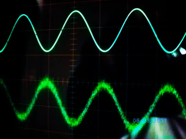
Image: Sine waves. The top line is a smooth sine wave of alternating current (AC.) The bottom line is a sine wave corrupted with EMI.
The analogy of wind and water wonderfully illustrates the concept of EMI.
If there is a slow and easy breeze moving across the surface of a lake, you will see ripples or small mercurial waves in the water.

Image: Calm waters.
When wind velocity and force increases, you will see more turbulent water. This resembles EMI.

Image: Rough waters.
The concern for EMI is the original reason your airline pilot calmly orders you to place your phone on “airplane mode.” Although the chance for occurrence is highly remote due to EMI preventative safety designs, electromagnetism from the many cell phones reflecting off hard surfaces inside the cabin could intrude onto the computer’s circuitry that controls the landing gear.
EMI is why particular hospital wings will have cell phone-restricted areas.
Image: No Cellphones Allowed.
If you think that your fine electronics may be affected by EMI, then you are on on your way to having your problem solved. We’re here for you from Monday through Friday.
©2022 All rights reserved.